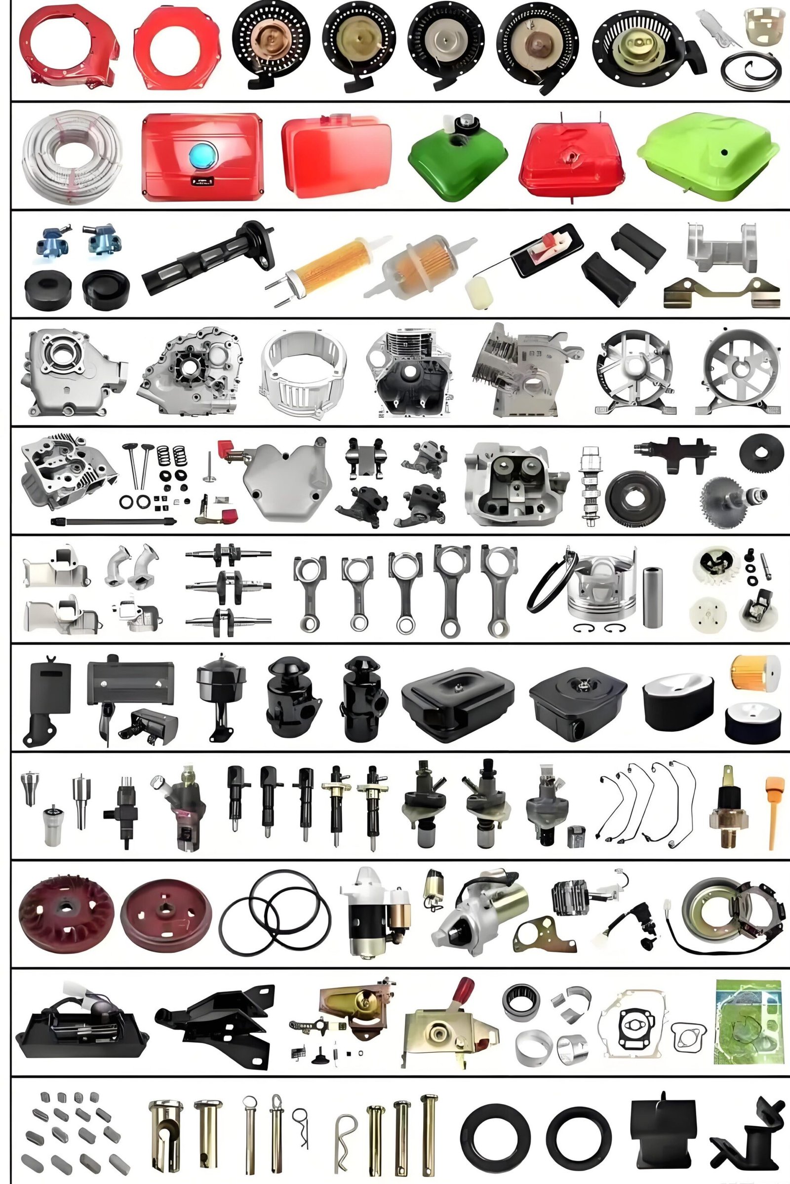
Components/accessories of a small portable gasoline generator
Small portable gasoline generators consist of four main hardware groups: ignition, fuel, power regulation, and frame/hardware. The ignition system includes the flywheel magneto, ignition module, and spark plug, which together generate and time the high-voltage spark. Fuel is metered and atomized by a carburetor, controlled by a petcock and protected by a sediment screen. Output voltage is stabilized either by an automatic voltage regulator in conventional sets or by a permanent-magnet generator plus inverter in variable-speed units, the latter delivering cleaner sine waves for sensitive electronics. Mobility and durability are provided by powder-coated steel carry frames, vibration-isolating rubber feet, and optional lockable canopies. Routine-maintenance items—air filters, low-oil sensors, and mufflers—ensure reliable, quiet operation and long engine life.
Section 1 – Narrative (arranged by functional system)
- Ignition system
The ignition module (TCI or CDI) is the “heart” of a gasoline engine. It steps up the low-voltage current from the flywheel magneto and delivers a high-voltage pulse to the spark plug at the correct time. The flywheel itself contains embedded permanent magnets; as it spins it both powers the ignition module and, on battery-equipped sets, charges the battery. The spark plug conducts the high-voltage arc into the combustion chamber; electrode gap and heat range must match the engine specification, otherwise idle instability or pre-ignition can occur. - Fuel-supply system
The carburetor uses intake vacuum to atomize gasoline and create a combustible mixture. Inside it, the main jet, pilot jet and float needle are normal wear items. The fuel petcock (fuel outlet valve) is often designed for 90° quick shut-off to prevent leakage during transport. Many models include a detachable sediment bowl that traps water and dirt, reducing carburetor malfunctions. - Power-output & voltage-regulation system
Conventional sets use an Automatic Voltage Regulator (AVR) that senses output voltage and adjusts excitation current to keep 230 V (or 120 V) within ±3 %. Inverter sets omit the AVR; instead they employ a “permanent-magnet generator + inverter (converter)” topology: the AC is first rectified to DC, then inverted back to 50 Hz (or 60 Hz) AC with <3 % THD—safe for laptops and sensitive instruments. For outdoor work, receptacles should be the locking, weather-proof type to avoid accidental disconnection. - Frame & mobility parts
Carry frames or folding handles are usually welded from 22 mm steel tube and 3 mm plate, then powder-coated to ≥80 µm thickness so they pass a 48 h salt-spray test without rust. Anti-vibration foot pads are a rubber–steel sandwich (65±5 Shore A SBR) that cut vibration noise by 5–8 dB. RV or truck-air-conditioner units can be fitted with full-coverage anti-theft canopies made from 1.2 mm perforated steel for ventilation and security. - Protection & maintenance items
Air-filter elements are either dry paper or oiled foam: the foam type is washable but must be cleaned every 8 h in dusty sites; the paper type is disposable. The low-oil sensor uses a magnetic reed switch that grounds the ignition when oil falls below the safe level, preventing seizure. The muffler contains dual baffles and glass-fiber wool to lower exhaust noise by 10–15 dB; when the wool disintegrates the exhaust note becomes “crackly” and the whole muffler should be replaced.
Section 2 – Detailed spare-parts table
| Major group | Sub-part / component name | Primary function | Typical mounting location | Normal service life or change interval |
|---|---|---|---|---|
| Ignition | Ignition module (TCI / CDI) | Voltage step-up & timing | Beside flywheel or inside panel | 1 000 h, or when misfire occurs |
| Ignition | Flywheel | Energy storage, cooling, triggering | Front end of crankshaft | Designed ≥2 000 h; replace if impact-deformed |
| Ignition | Charging coil | Power generation | Fixed around flywheel rim | 1 000–1 500 h |
| Ignition | Spark plug | Ignite mixture | Cylinder-head top | Clean carbon every 100 h, replace at 300 h |
| Fuel | Carburetor assembly | Atomize fuel | Between air filter & head | Clean every 500 h, replace jets when worn |
| Fuel | Fuel petcock / outlet valve | On/off control | Bottom of fuel tank | Replace when seal hardens / leaks |
| Fuel | Sediment cup + screen | Water / dirt trap | Below petcock | Drain every 30 h, replace screen if torn |
| Power | AVR regulator | Voltage stabilization | Rear end-cover or panel | 800–1 200 h |
| Power | Inverter (converter) | AC-DC-AC conversion | Fan-cooled box on inverter sets | Designed 2 000 h; heat is main killer |
| Power | PM stator / rotor | Power generation | Inside brushless inverter genset | 1 500 h; check if bearing noise appears |
| Power | Output receptacle | Power take-off | Control panel | 2 000 insertions or when loose |
| Frame | Carry frame / handle set | Load bearing, portability | Around entire set | Re-paint or replace if rust >5 % area |
| Frame | Anti-vibration foot pads | Damping & noise reduction | Four corners of base | Replace when cracked (2–3 years typical) |
| Maintenance | Air filter (paper or foam) | Dust filtration | Carburetor inlet | Paper: 50 h; foam: wash every 30 h |
| Maintenance | Low-oil sensor | Low-oil shutdown | Crankcase side wall | 500 h, or if false alarms appear |
| Maintenance | Muffler / silencer | Noise reduction | Cylinder-head exhaust port | Replace when fiber wool disintegrates |
Note: Intervals may be shortened in dusty, high-temperature or continuous-load conditions. If output drops, unusual noise, blue/white smoke or voltage instability appear, inspect the related parts first.